

For about two weeks i have all the parts to start my assembly. As soon as i got my steel frame i took my dimensions of the profiles and started printing my jigs and functional parts.
The dimensions they advertise online and the real world dimensions differered in my case about 0.5mm. So always make sure you measure on your steel before starting to print.
This post will be about assembling the steel frame and connect it to all the mechanical parts (linear rails, ball, screws, etc.).
There is a, bit outdated, but very detailed assemby guide on the PrintNC wiki i follow along: Link
I will not do a full build guide, just follow along the official PrintNC assembly guide, that will be much more detailed.
Prepare the steel profiles
time required: 6-8 hours
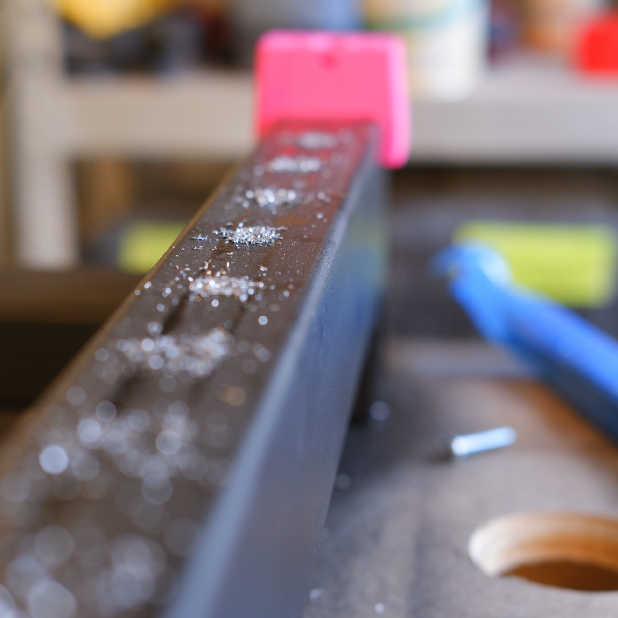
While the printer was running 24/7 i started working on the steel profiles. They had pretty big scratch marks, some flight rust, rough edges and imperfections from the welding process.
I sanded them on all the edges and faces as you can see in the video below.
Painting the steel
time required: 2-4 hours
After all the sanding was done i cleaned the profiles with a dry cloth and a shop vac to remove all the small chips from the sanding process.
I then layed the profiles outside and cleaned them with acetone. I ordered the cheapest paint from ebay (6x 500ml cans for 19,95€) and started spray painting all the steel. I put a wooden rod through the beam so i can spray paint it from all the sides at once.
I painted three coats and was ready for drilling.
Drilling and threading of the main frame
time required: 5-6 hours
Just follow the assembly guide rigorously for this part because it is still up to date for the base frame. You place the jigs in position and mark and thread the holes according to the description.
Try your best to be really careful to drill and thread everything as straight as possible. Especially if you only have an automatic center punch like i did.
For the deeper holes in the bearing mounts i used a drill bit instead of the automatic center punch to reduce the wiggle room as much as possible.
I threaded all the holes with a “classical” thread cutter. Don`t be like me and buy a cheap combo drill and tap bit and save yourself a lot of time.
Frame assembly
time required: 2 hours
After you drilled all the holes you can start the assembly of the main frame. in my case that means three crossbeams and two wide beams.
Detailed view of one of the screwed in place crossbeams
You dont just screw everything together in this step, you also try your best to square everything as good as possible.
After i completed the main frame, i gave it another coat of matte black to cover up minor scratches from the assembly process.
In the following picture you can see the fully assembled main frame:
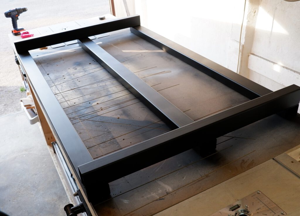
y-axis mechanics
time required: 10-12 hours ( i was slow on this one)
With the finished base frame in place i could start with the assembly of the mechanical components of the y-axis.
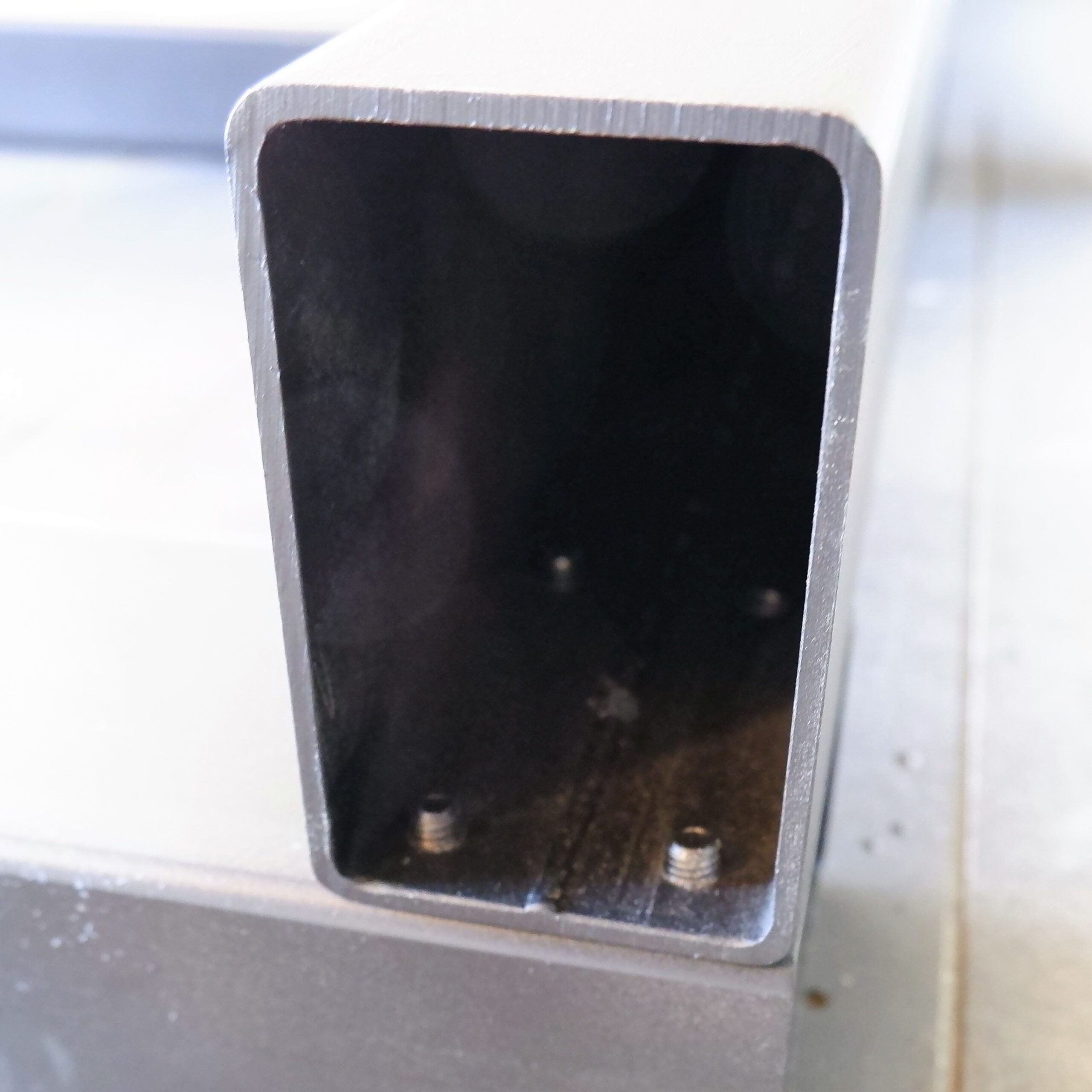
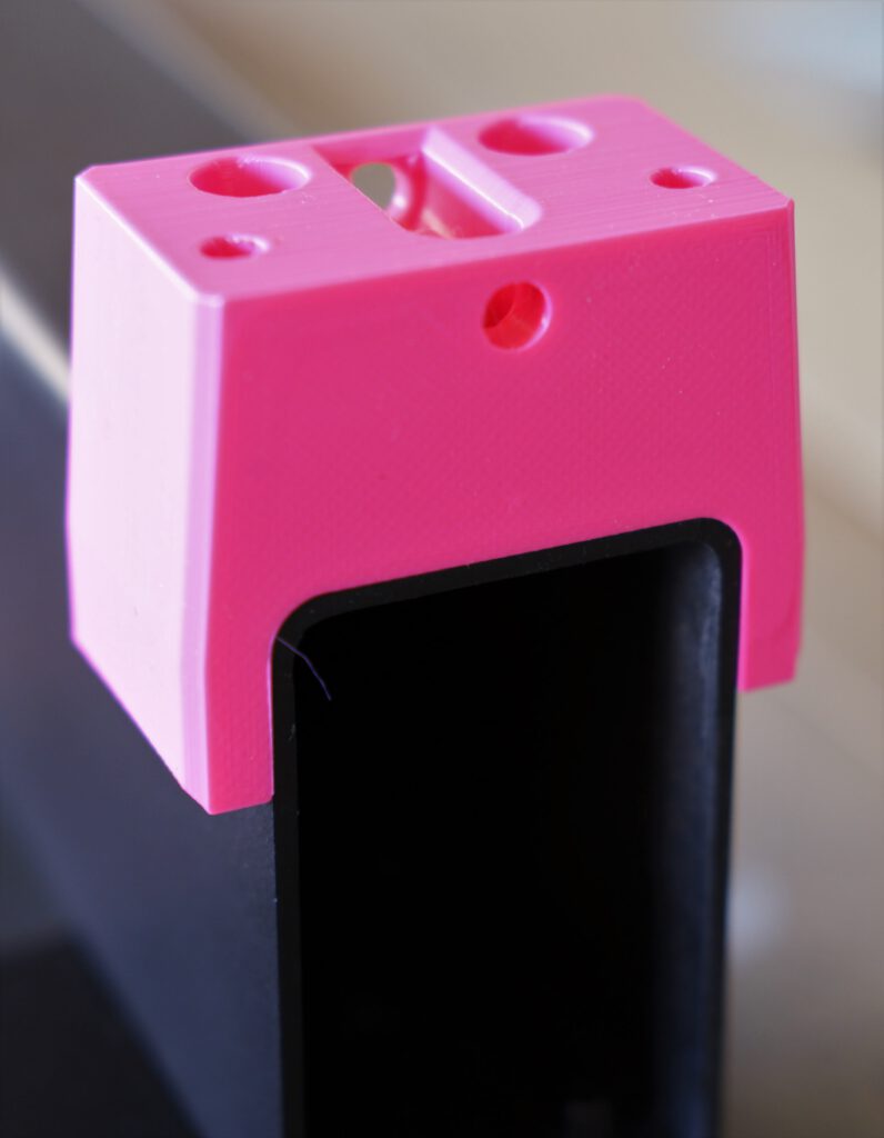
You start out with the bearing blocks. You can see the pretty much perfect fit of the printed parts on the steel frame. The hours with the belt sander paid of.
After screwing the bearing blocks in place you start mounting the linear rails. A lot of M5 threads have to be cut here.
You 100% have to use the center jigs from the mod section to align the rails on your frame. To have as little play as possible, i used a drill bit and a soft hit with the hammer to mark the holes. After i took the rails of i used the center punch on the marked spots.
Just make sure, to be as precise as possible, otherwise your rails will not be centered.

When you are done with mounting the rails, it`s time to prepare the y-rollers and mount them on the linear guides. Here are some pictures of the process:
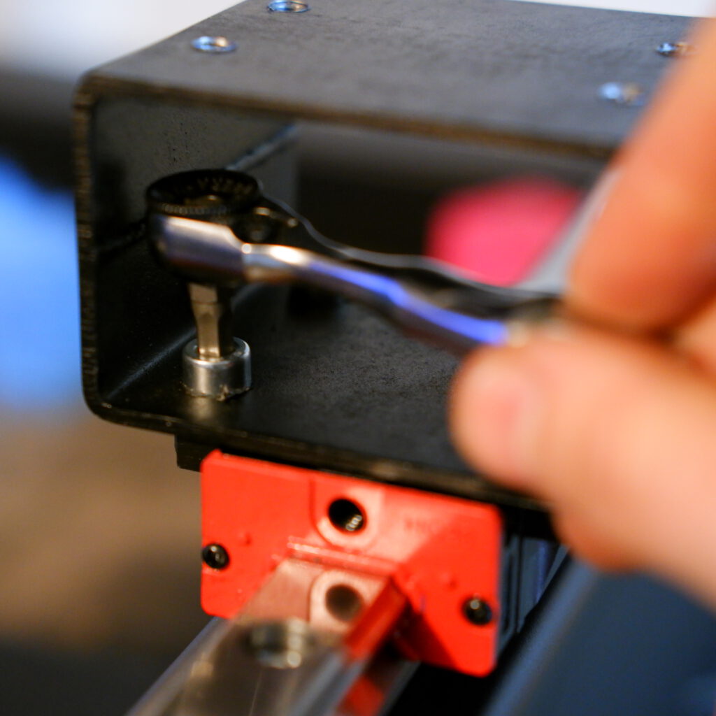
These are pretty tricky to install because of the tight dimensions inside the profile. I had a mini ratchet that fit the job perfectly.
You don´t necesarily need pan head screws as the guide describes. Cylindrical ones work fine too.
Also dont be like me and make sure you mount the grease fittings before you put the carriages on the rails.
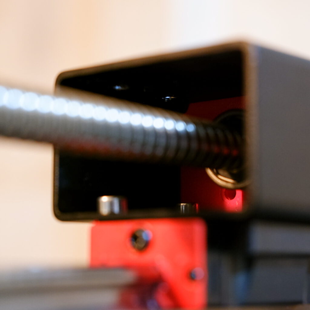
In this picture you can see the ballscrew fed through the middle of the y-rollers.
Be very gentle when inserting the ball screw into the bearing blocks, use a lot of oil and minimal force. The parts are toleranced very tightly so this part can be a bit tricky.
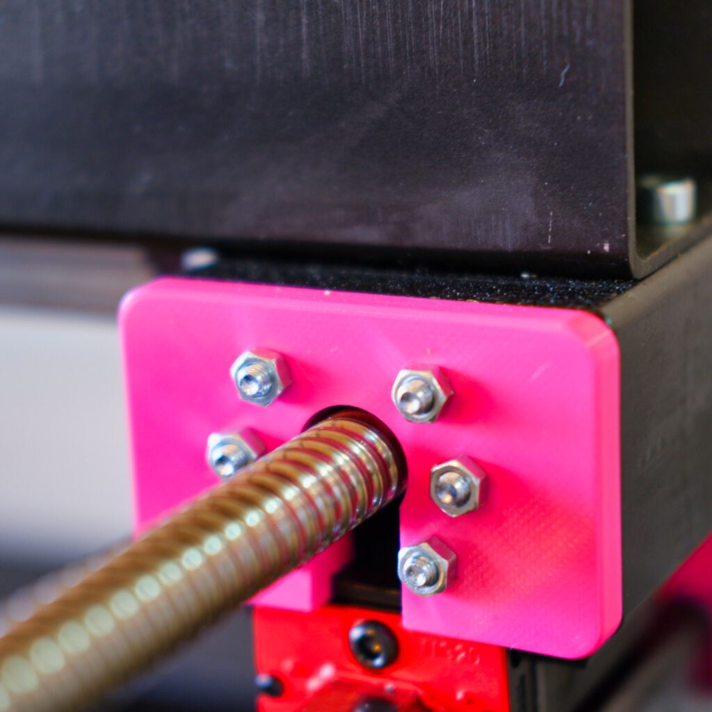
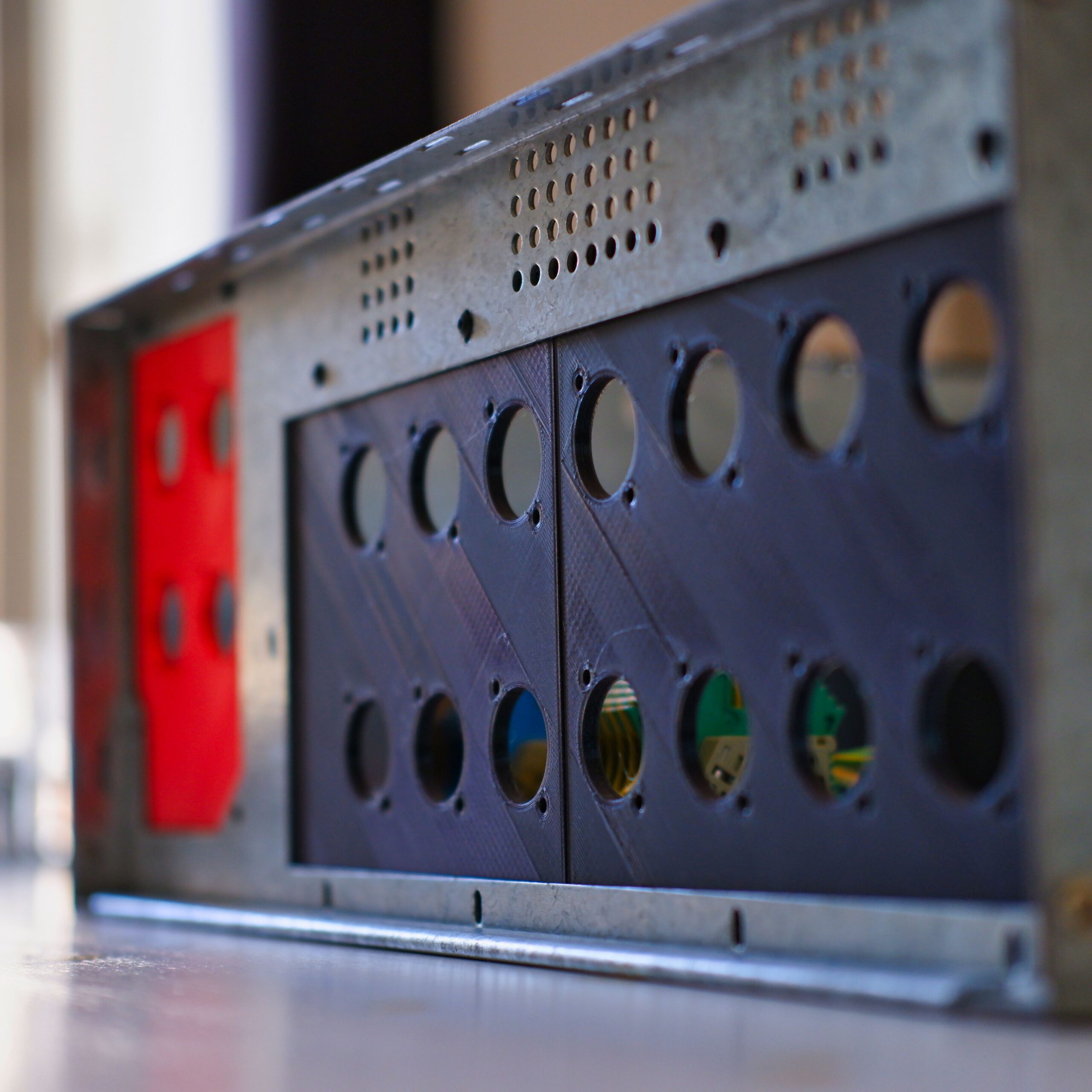
In the next step you guide the six screws through the ball screw mount and the two y roller side faceplates.
When printing the faceplates make sure you get a nice tight fit to the ball screw mounting plate.
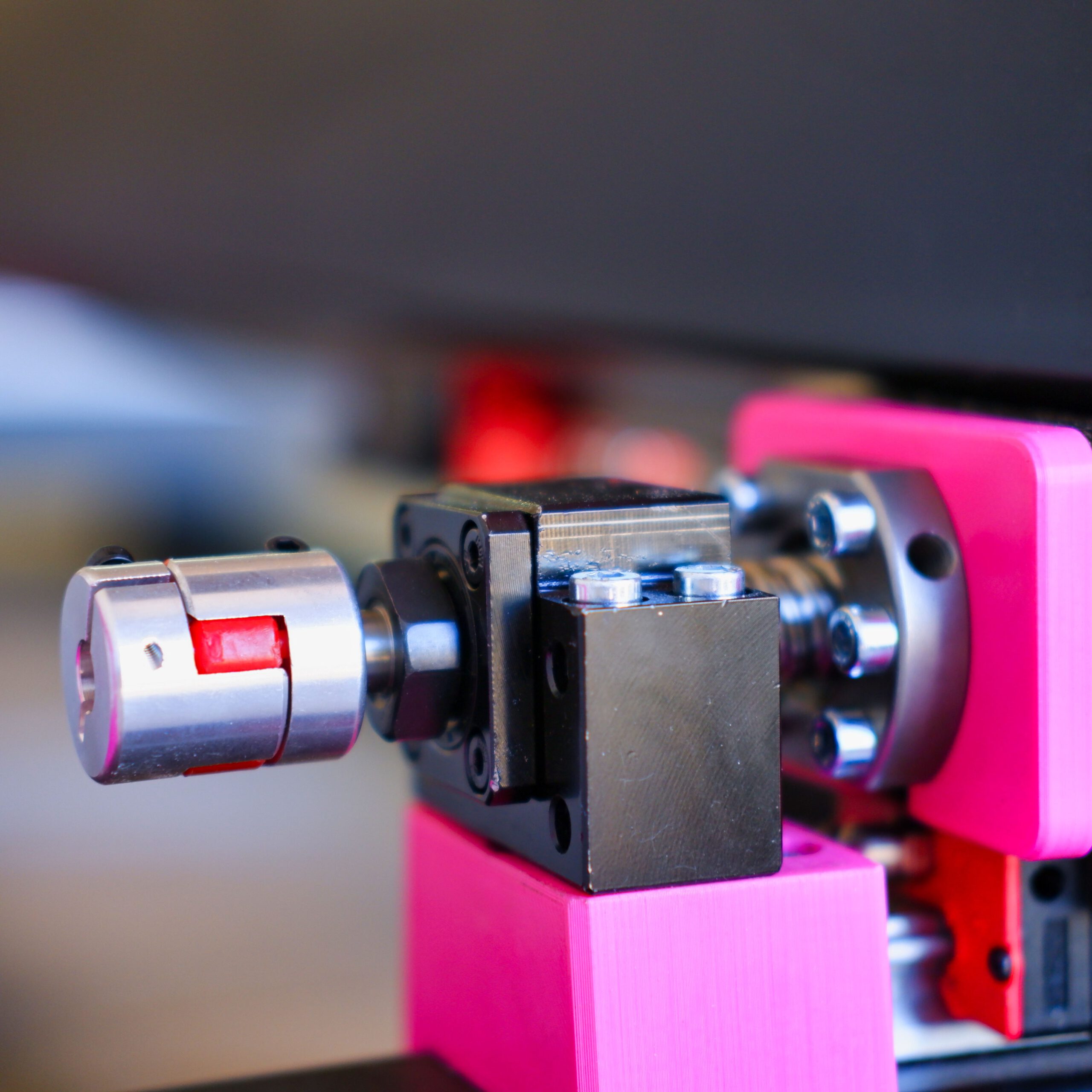
After finishing this step i greased all the parts and did a test run with my power drill connected to the ball screw:
x-axis mechanics
time required: 4-5 hours
For the x-axis, spacing/locating the parts is a bit different. You either place all your parts (ballscrew, bearing blocks, motor mount) on the x axis and figure out how to maximize your travel area or you go to your Fusion360 model and measure the distances put the parts in place accordingly.
I went with the first version.
Starting with the drilling the holes for the bearing blocks, center align the linear rail, drill the two outer holes for the linear rail, tap them and screw it in place. Then mark, drill and tap all the holes for the linear rail on the top side.
This step was pretty time consuming because i used a dedicated thread cutter and not a drill/tap bit.
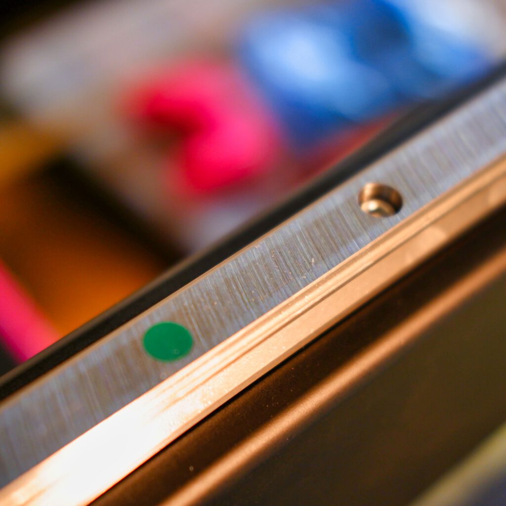
After screwing your linear rails in you put the dust covers in place. They are included in the Aliexpress-kit and have a pretty tight fit. I hammered them in place with a rubber mallet.
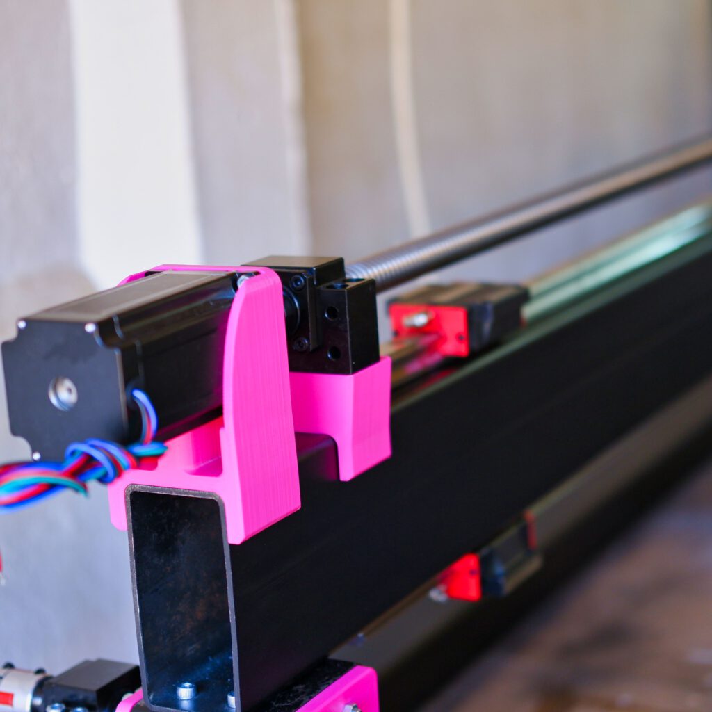
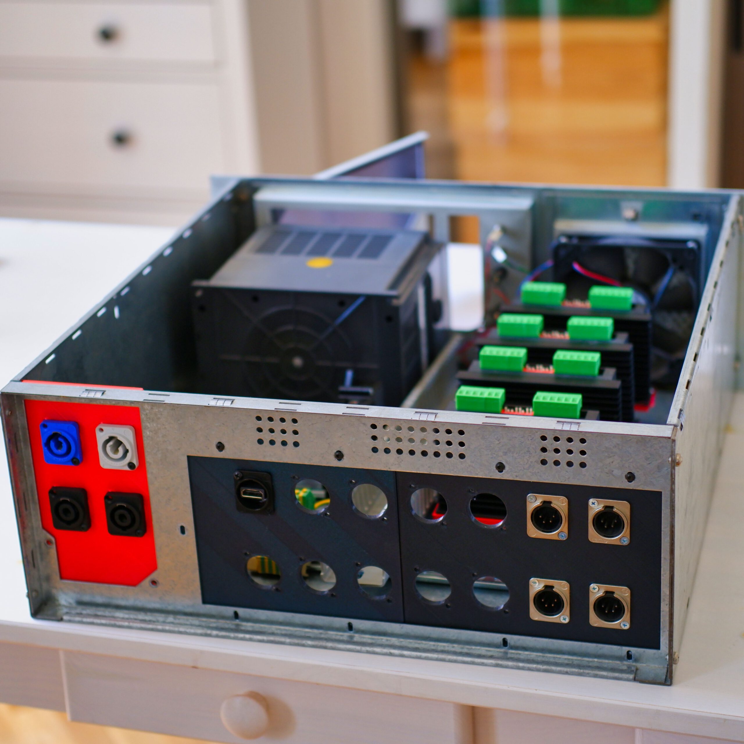
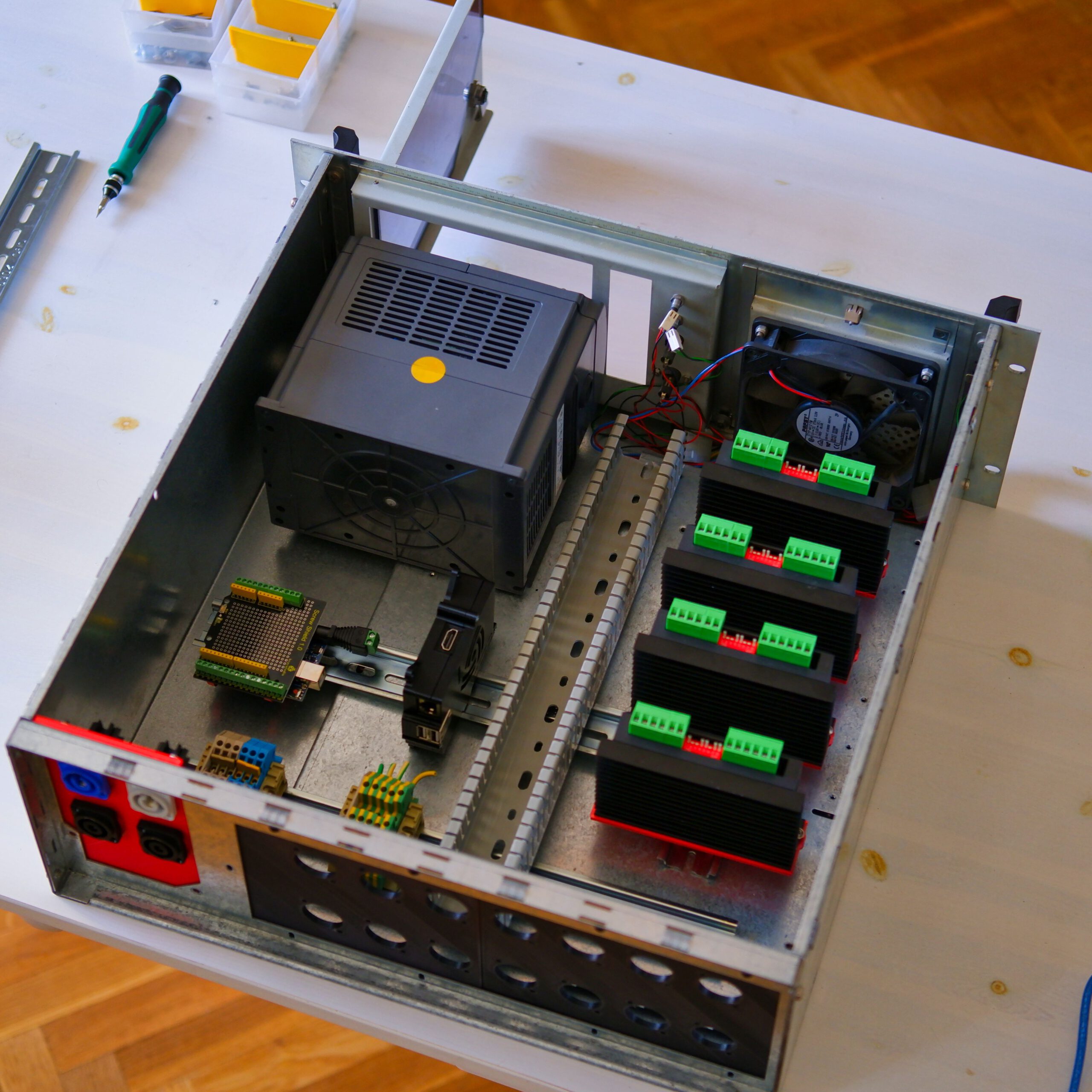
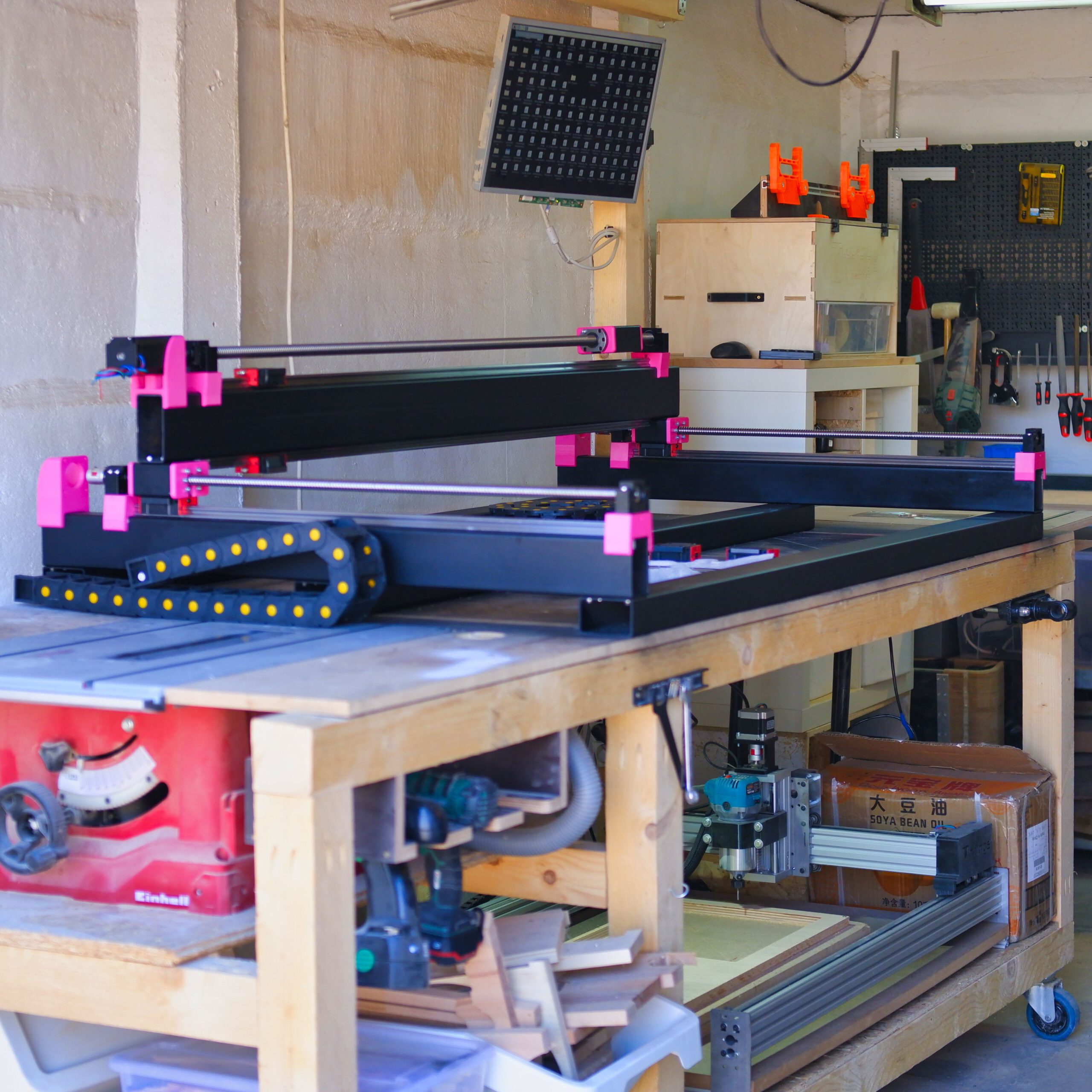
This is the progress picture of the second week, working on the mechanics. I’ll be working on the z-axis and the electronics in the upcoming week so stay tuned.

to be continued (z-axis and electronics are next)
Project Pictures


1 Comment
Add Yours →Thanks for sharing. Gives me a nice overview of what it takes to build this machine.